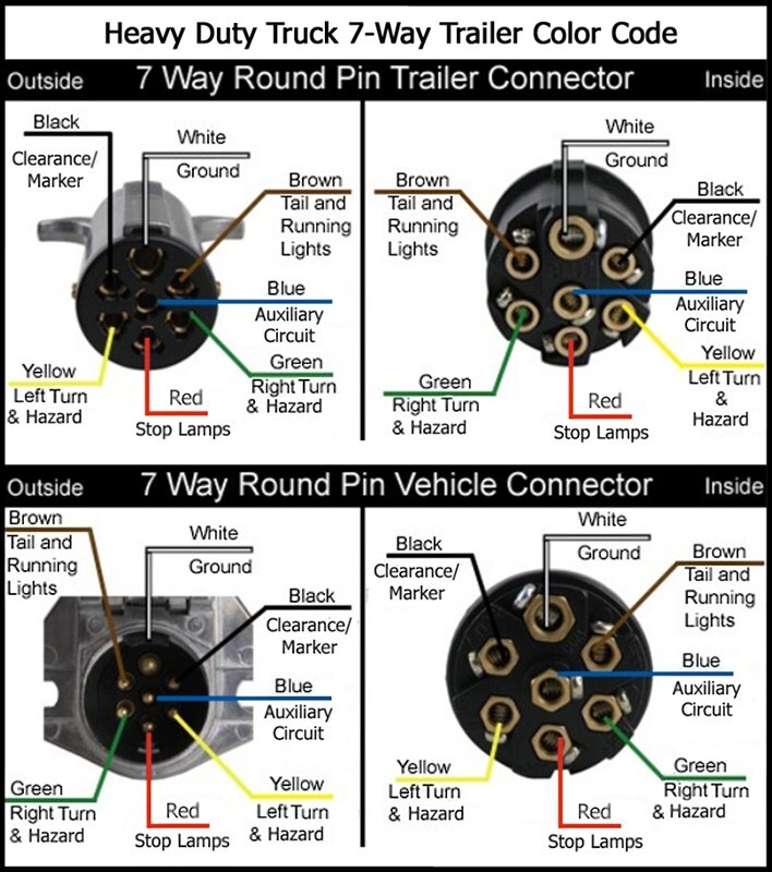
7 Pin Trailer Connector Diagram : Wiring Diagram for the Pollak Heavy-Duty, 7-Pole, Round Pin, Trailer Wiring Connector # PK11700 .... Variety of 7 pin round trailer wiring diagram. It shows the components of the circuit as simplified shapes, and the power and signal contacts between the devices. White pin to your ground. 7 way plug wiring diagram standard wiring* post purpose wire color tm park light green (+) battery feed black rt right turn/brake light brown lt left turn/brake light red s trailer electric brakes blue gd ground white a accessory yellow this is the most common (standard) wiring scheme for rv plugs and the one used by major auto manufacturers today. The safety and security of all persons on or off the road, as well as those operating a motorized vehicle, depends on knowing exactly how.
You simply require to have a excellent understanding on various types of wiring and their purposes. The 7 pin n type plug and socket is still the most common connector for towing. If you are looking at the inside of the trailer connector where the wires mount to the terminals starting at the top and rotating clockwise: Brown 7 tail lights/clearance markers diagrams are from cable entry view tdr06904 part number 1 6 5 3 2 7 4 tdr06905 part number 4 7 2 3 5 6 1 7 pin round large plastic trailer socket 7 pin round large metal trailer socket 7 pin flat plastic trailer socket 7 pin flat plastic trailer plug 7 pin round large plastic trailer plug 7 pin round large. Brown pin for side markers, tail lights, and running lights.
Ford 7 Pin Trailer Wiring | schematic and wiring diagram from i.pinimg.com Brown pin for side markers, tail lights, and running lights. Oct 10, 2016 at 9:48 pm #1 #1. For example , when a module will be powered up also it sends out a signal of half the voltage in addition to the technician will not know this, he'd. 7 pin trailer connector wiring diagram. This 7 pin trailer wiring diagram chevy model is far more suitable for sophisticated trailers and rvs. Below is a diagram for the original plug and socket showing the functions of each pin. This supplies power to the road lighting of your trailer or caravan. 7 way plug wiring diagram standard wiring* post purpose wire color tm park light green (+) battery feed black rt right turn/brake light brown lt left turn/brake light red s trailer electric brakes blue gd ground white a accessory yellow this is the most common (standard) wiring scheme for rv plugs and the one used by major auto manufacturers today.
White pin to your floor.
This freightliner trailer wiring diagram model is far more appropriate for sophisticated trailers and rvs. 1:00 is black and 12 volt power. The safety and security of all individuals on or off the road, as well as those operating a mechanized lorry, depends on. Oct 10, 2016 at 9:48 pm #1 #1. A wiring diagram usually gives suggestion very nearly the relative incline and bargain of. This wiring diagram for 7 pin trailer plug model is far more suitable for sophisticated trailers and rvs. Brown 7 tail lights/clearance markers diagrams are from cable entry view tdr06904 part number 1 6 5 3 2 7 4 tdr06905 part number 4 7 2 3 5 6 1 7 pin round large plastic trailer socket 7 pin round large metal trailer socket 7 pin flat plastic trailer socket 7 pin flat plastic trailer plug 7 pin round large plastic trailer plug 7 pin round large. This has now been replaced by 13 pin euro plugs on all new caravans. 7 way plug wiring diagram standard wiring* post purpose wire color tm park light green (+) battery feed black rt right turn/brake light brown lt left turn/brake light red s trailer electric brakes blue gd ground white a accessory yellow this is the most common (standard) wiring scheme for rv plugs and the one used by major auto manufacturers today. Ford 7 pin trailer connector wiring diagram from www.trailerjacks.com. We have an excellent wiring diagram on our website, i will provide you a link so you can look at it. If your vehicle is not equipped with a working trailer wiring harness, there are a number of different solutions to provide the perfect fit for. White pin to your floor.
This freightliner trailer wiring diagram model is far more appropriate for sophisticated trailers and rvs. 5:00 is blue and brake controller. This has now been replaced by 13 pin euro plugs on all new caravans. Most of us aren't electricians, but that doesn't mean wiring a trailer or replacing corroded wiring is beyond us. We have an excellent wiring diagram on our website, i will provide you a link so you can look at it.
Trailer Plug 7 Pin Wiring Diagram | Trailer Wiring Diagram from trailer-wiring-diagram.com A wiring diagram usually gives assistance very nearly the relative face and union of devices. Various connectors are available from four to seven pins that allow for the transfer of power for the lighting as well as auxiliary functions such as an electric trailer brake controller, backup lights, or a 12v power supply for a winch or interior trailer lights. 1:00 is black and 12 volt power. If you are looking at the inside of the trailer connector where the wires mount to the terminals starting at the top and rotating clockwise: The wiring diagram is normally made use of in electrical design to plan the positioning of electrical circuits. Choose a connector that has the required number of. This freightliner trailer wiring diagram model is far more appropriate for sophisticated trailers and rvs. This wiring diagram for 7 pin trailer plug model is far more suitable for sophisticated trailers and rvs.
You simply require to have a excellent understanding on various types of wiring and their purposes.
Below is a diagram for the original plug and socket showing the functions of each pin. For example , when a module will be powered up also it sends out a signal of half the voltage in addition to the technician will not know this, he'd. The wiring diagram is normally made use of in electrical design to plan the positioning of electrical circuits. Trailer electrical connectors come in a variety of shapes and sizes. Ford 7 pin trailer connector wiring diagram from www.trailerjacks.com. 7 pin trailer plug light wiring diagram color code. The safety and security of all persons on or off the road, as well as those operating a motorized vehicle, depends on knowing exactly how. Most of us aren't electricians, but that doesn't mean wiring a trailer or replacing corroded wiring is beyond us. Brown 7 tail lights/clearance markers diagrams are from cable entry view tdr06904 part number 1 6 5 3 2 7 4 tdr06905 part number 4 7 2 3 5 6 1 7 pin round large plastic trailer socket 7 pin round large metal trailer socket 7 pin flat plastic trailer socket 7 pin flat plastic trailer plug 7 pin round large plastic trailer plug 7 pin round large. 1:00 is black and 12 volt power. Wiring diagram trailer plugs and sockets. This has now been replaced by 13 pin euro plugs on all new caravans. Each component ought to be set and connected with different parts in particular manner.
A wiring diagram usually gives suggestion very nearly the relative incline and bargain of. 7 pin trailer connector wiring diagram. If not, the arrangement will not function as it ought to be. The safety and security of all individuals on or off the road, as well as those operating a mechanized lorry, depends on. Variety of 7 pin round trailer wiring diagram.
Wiring Diagram for a 1997 Peterbilt Semi Tractor with 7-Pin Round Connector | etrailer.com from www.etrailer.com Choose a connector that has the required number of. Below is a diagram for the original plug and socket showing the functions of each pin. 5:00 is blue and brake controller. It shows the components of the circuit as simplified shapes, and the power and signal contacts between the devices. By law, trailer lighting must be connected into the tow vehicle's wiring system to provide trailer running lights, turn signals and brake lights. The safety and security of all persons on or off the road, as well as those operating a motorized vehicle, depends on knowing exactly how. 1:00 is black and 12 volt power. In the trailer wiring diagram and connector application chart below, use the first 5 pins, and ignore the rest.
You simply require to have a excellent understanding on various types of wiring and their purposes.
When autocomplete results are available use up and down arrows to review and enter to select. Wiring diagram trailer plugs and sockets. White pin to your ground. Trailer electrical connectors come in a variety of shapes and sizes. A wiring diagram usually gives suggestion very nearly the relative incline and bargain of. In the trailer wiring diagram and connector application chart below, use the first 5 pins, and ignore the rest. If not, the arrangement won't work as it should be. If not, the arrangement will not function as it ought to be. Oct 10, 2016 at 9:48 pm #1 #1. Below is a diagram for the original plug and socket showing the functions of each pin. Variety of 7 pin round trailer wiring diagram. It shows the components of the circuit as simplified shapes, and the power and signal contacts between the devices. 3:00 is green and right turn and brake.


0 Comments:
Posting Komentar